
Fusion Generator:Kresty Style Build:Top
Back to Kresty Style Build guide page.
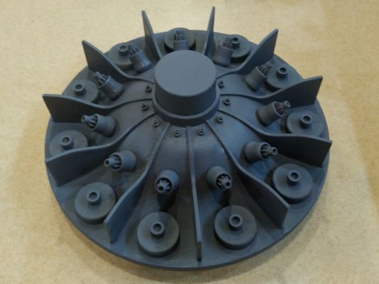
The top contains primarily 3D printed parts.
Important: Before assembling, make sure you know at which point you want to Remove The Top. Savage Creature's plans have ring M just below the 3D printed top segments, with the intent of removing the top from the M ring to access the inside. Kresty messed up and glued the ring to the top segments, so he had to figure out a different way to separate the top.
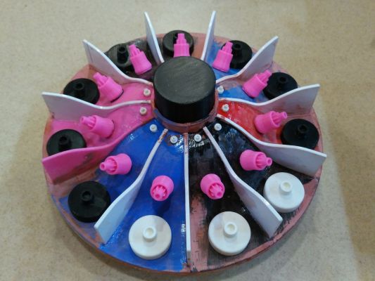
Top Segments
The top has 11 segments divided by the vanes. Probably originally an industrial motor fan. The foundation of our build's top consists of 5 "double" segments and 1 "single" segment. They have tabs on one side that lock into holes onto the other side.
Each segment also has holes for the tiny "Coil Socket" at the top, and the "Heatsink" in the middle. The pad for the lower "Coil Mount" is at the bottom. The double segments and edges of all segments also have two slots for the vanes.
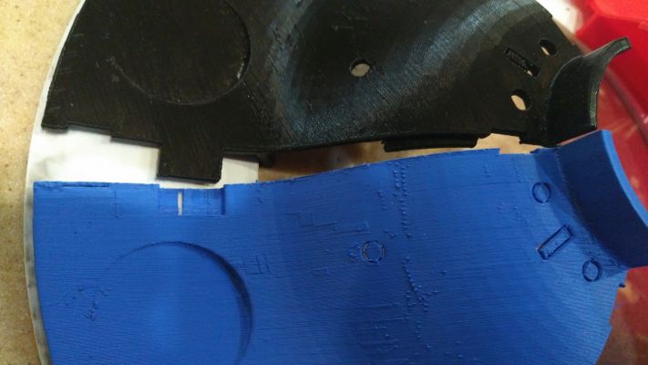
Those support holes need removed and the edges may need cleaned up.
Top Ring
The top 3D printed segments have a lip that fits into the top "M" ring. You may need to sand the assembled 3D top segments or the inside of the ring a little to get them to fit. (Your V3 "M" ring will have better mounting holes for the lower parts than my V1 ring pictured below.)
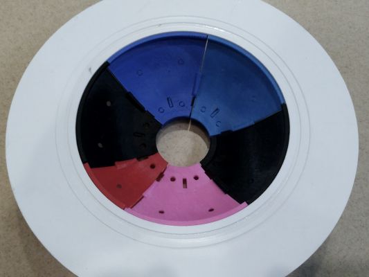
Savage's original plans expect for the top 3D segments and the "M" ring to remain unglued so that the top of the Fusion Generator can be removed here. I accidentally glued them together, so had to do it differently. I've listed some Pros and Cons of the different places to remove the top.
Light Leaks
You may want to putty the top ring before adding the greeblies so it's easier to apply and sand. When puttying you may want to consider light leaks.
Presumably you'll illuminate the interior somehow. I shined a light from the bottom to help locate cracks where light might leak when on display and filled those from the inside (I actually just smeared on ABS pipe glue to clog those holes, quick and dirty)
Greeblies
We kept the top cap separate for painting. You may want to attach some or all of the segments, particularly the heatsink fins, after painting.
- The top cap fits in the middle of the 11 segments.
- Glue may not be required
- We painted ours separately so that it could stay silver-y.
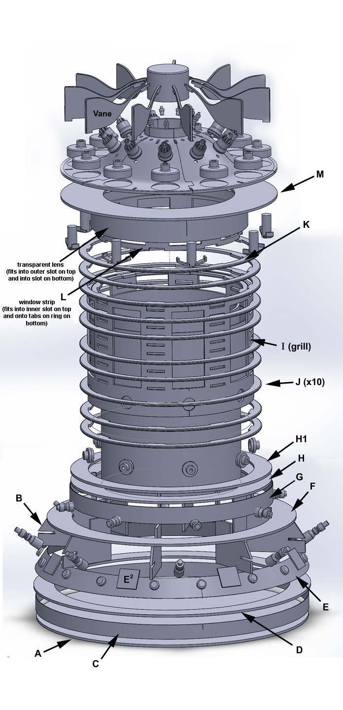
- The 11 Vanes fit with their tabs in the slots between each segment.
- The 11 large Coil Mounts fit the recesses along the bottom of each segment.
- More details about the Top Coils themselves
- Holes for the 11 tiny coil sockets are on the top of each segment.
- The 11 heat sinks in the middle are 3 parts.
- The main part has a small post on the bottom and heatsink in the top center.
- You may want to paint the fins before gluing them to the main body of the heatsinks. (I split them up because I had difficulty reaching the insides of the heatsinks)
- There are 8 T fittings on the bottom of the M Ring. Those have a slot for a translucent peg to attach the hose. Don't attach the peg until after painting.
Top Assembly
Printing in ABS and laser cutting in Styrene most plastic model glues should work, like plastic cements, solvents, or CA glue. You may want to test your bond before committing. We used MEK because it was handy, however it is pretty nasty stuff so I'm not going to recommend that. Our technique did poorly for other points.
- Make sure you know where you want your top to be removed. (Pros & Cons)
- Punch out the holes and clean up the edges of the top segments as needed.
- Test fit that the top segments assemble OK and fit in middle of Ring M.
- Sand if needed.
- Glue the top segments.
- If desired, you may glue to Ring M. Pros and cons.
- We assembled them all and then glued the segments one at a time.
- Clamps can help. Also tape around the center can help.
- Ring M can be used as a jig even if you don't intend to glue the top to Ring M - however, use care to avoid accidental adhesion!
- Attach the Vanes
- You may need to sand the tabs or holes a little to fit.
- At this point you can apply plastic filler/putty and sand as desired.
- Attach the Greeblies that you intend to paint as one unit.
- If you want parts a different color or something, then wait until the top is painted before attaching.
- I would keep out the "fins" of the heat sinks and the top cap.
- Don't install the translucent pegs to the bottom of the T fittings until after painting.
- Prime and paint the parts.
- Glue any Greeblies held back for painting.
- You may install the translucent pegs to the bottom of the T fittings at this time.
- Attach the Top Coils.
Note that though all the parts are primed here, the top cap and heatsink fins aren't bonded so I can paint them separately.
Notes
The texture of the 3D prints can be used to great effect, so we didn't try to perfectly putty and smooth the printed segments.
Pros and Cons of where to separate the top.
Back to Kresty Style Build guide page.
Forward to Middle Grill Assembly
Skip forward to Base Assembly