
Fusion Generator:Kresty Style Build:Base
Back to Kresty Style Build guide page.
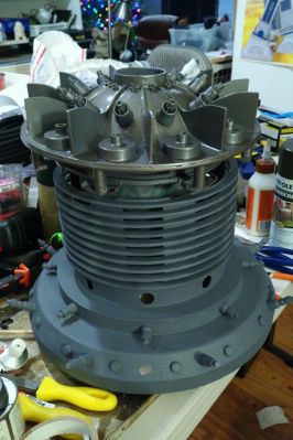
This is the base section of the fusion generator, the laser cut Styrene parts. Shown here without the 3D printed greeblies.
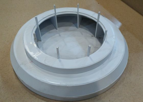
Note that Kresty built a too-tall version with extra C band and D ring - those aren't in the newer V3 plans, so ignore that bottom vertical section.
Contents
Decision Points
Before assembly, it is important to determine where you want to remove the top. Between the Grill and the Base is a decent choice.
If you want to provide a socket for a real or Prop Power Cord, it would be good to think about how that is going to work before fitting the parts of the base.
Fusion Generator Base
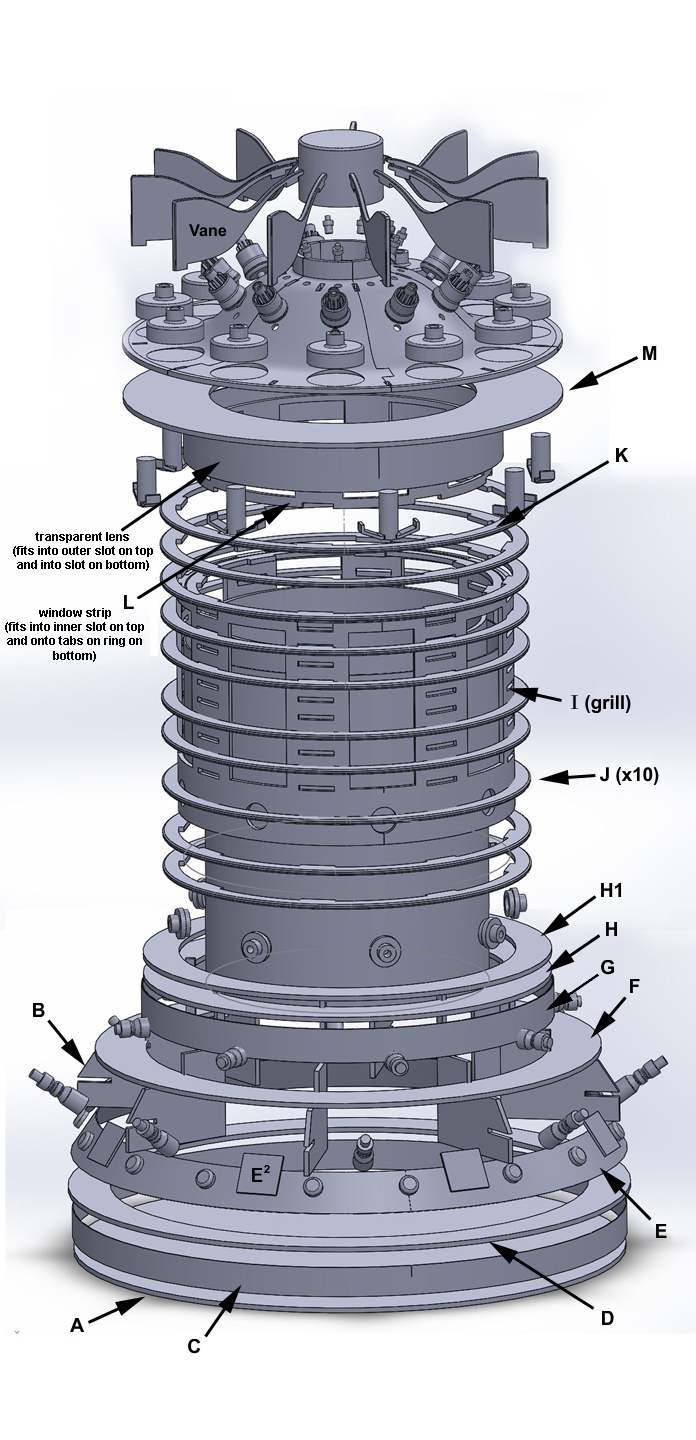
The base consists of the A disc, F, H & H1 rings, with the E and G bands strapped around it. The bands have 3D greebles. After painting, the Lower Hoses are added. We have an Alignment Template to help mark the greeblie positions.
Start by placing the B supports on the A disc and test fitting the F & H rings. In this picture I have also placed some of the grill parts, and, as noted I have an extra D ring that isn't in the V3 plans.
After ensuring that the fit of the disc and rings are good, you can glue them with an appropriate styrene model cement or CA glue.
The split H1 rings can be easily glued once the H ring is attached. The outer edge of the H1 halves should line up with the outside edge of the H ring, leaving a gap between the inside of the H ring and the B support sticks where the lower edge of the grill should fit reasonably snugly.
Do not glue the grill to the H/H1 bands if you want the top and bottom to separate between the base and the grill.
Bands
The G band can simply be glued into place. I used one layer for the G band. If you use two layers, then I'd suggest alternating the seams. You may need to trim the band ends to fit or fill tiny gaps.
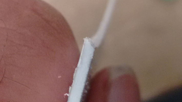
The E band is a bit tougher. We want the top and bottom edges of the E band to be filed so that it fits flat with the base and the F ring. File the top and bottom in the same direction at about 45 degrees. The cross section should then look like a parallelogram.
Putty
Savage must be used to cars, but I used the Bondo 907 Glazing and Spot Putty he recommended. Savage's thread has a good description of using the putty.
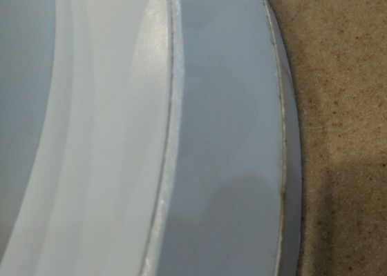
I slathered it on pretty heavily as I wanted to ensure that I got the edges of that E-band smoothed out. I was also a bit recessed in places (some of my parts were cut slightly too large, most people shouldn't have that problem.)
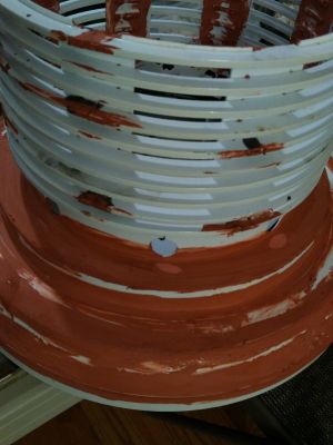
Note that when sanding it down we made the decision not to sand a perfectly smooth surface. There were a couple spots I could've added another thin layer of Bondo, but we decided that it'd add to the weathered look with some imperfections. You can see this around the hole that I repaired here.
Light Leaks
Presumably you'll illuminate the interior somehow. I shined a light inside to help locate cracks where light might leak when on display and filled those from the inside (I actually just smeared on ABS pipe glue to clog those holes, quick and dirty)
Greeblies
I puttied the bottom and primed it before using the Alignment Templates to mark the positions for the Greeblies. Unfortunately that meant my adhesive didn't work very well. CA glue should work OK at this point though.
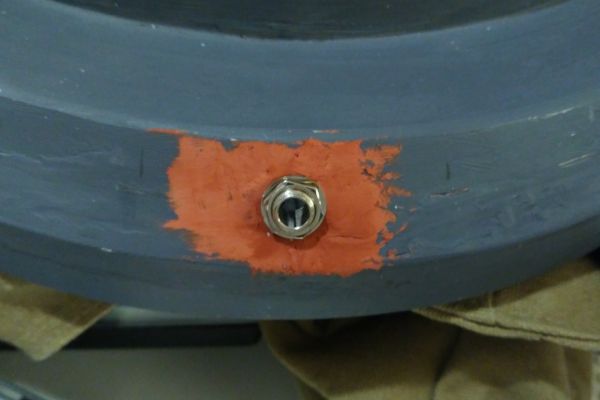
You may also want to decide if you want a hole for a "power cord" socket like I did above. If using the fusion generator to charge a droid you may want a connector appropriate for your system. I dummied in a hole (see above) for a fake cord. One of the hose nipple greeblies is modified to fit that socket.
If you decide to do something like that, you may want to ensure that you mark the positions for your greebles so that your hole does not end up positioned over one of the internal supports "B". (Mine did, and it was a serious pain to remove enough of the support for my fitting to work!)
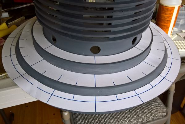
The 8 lower hose short nipples are centered under the holes in the grill on the centerline of the G band. Use the template to mark where to attach them every 45 degrees.
The E band has 32 greeblies in an alternating pattern. Every other one is a "button", with the round caps (squares marked E² in diagram) and longer lower hose angled nipples alternating for the remaining positions. Eg: button, round cap, button, long hose nipple, ...
You can use the template to mark the 32 positions for those greebles on the E Band. I chose to align the round caps to the upper short hose nipples, however SavageCreature's diagram appears to have a button in that position. Either way is probably fine as long as the short and long hose nipples are not aligned.
After marking them, you may place the Greeblies. CA glue should work.
If you want to paint some parts separately, you may add those later. I covered the mount point marks for the round caps with bits of painter's tape before priming everything as I wanted those to be silver.
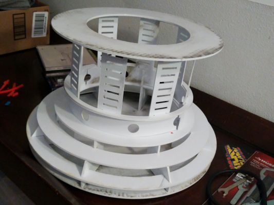
Test fit showing my greebles in place (along with the grill and top sections.) Note tat the locations for the round caps on the E band are covered with painter's tape so that I could find the marks after priming. This allowed us to paint those separately in a different color than the main base.
After painting, you'll want to attach the Lower Hoses.
Bottom Assembly
With ABS and styrene (polystyrene) parts, most plastic model glues should work, such as plastic cements, solvents, or CA glue. You may want to test your bond before committing.
- Fit the Disc A, Supports B and Rings F & H to ensure they fit
- Glue those together using appropriate model glue.
- Glue the H1 ring halves to the top of the H ring
- Make sure to allow room for the grill to fit between the H1 Ring and the posts of the B supports.
- Attach the G band pieces. You may need to clamp or tape them in place.
- File the top and bottom of the E band halves at about a 45 degree angle.
- The top and bottom edges should go in the same direction, so the end should look like a parallelogram.
- Test fitting it helps visualize what needs filed.
- When happy with the fit of the filed parts, glue the E band halves in place.
- Use model putty as needed to fill in the gaps.
- Check for light leaks and fill as needed.
- When happy with the sanding, use the template to mark the greeblie positions.
- If using a real or fake "power cord", ensure you don't collide with an interior support.
- The short hose nipples should align with the 8 holes on the grill.
- If doing a special power cord fitting, you may want to place that appropriately.
- Place the greeblies as appropriate.
- If you want to paint some differently, leave those off.
- Prime and paint the parts
- Install remaining greeblies
- Install Lower Hoses
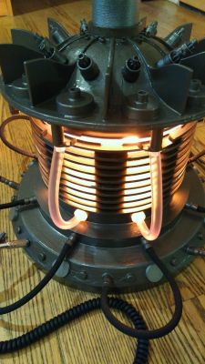
Shown with hoses and upper sections in place. Note the round caps were left silver compared to the primary color of the rest of the fusion generator.
Pros and Cons of where to separate the top.
Back to Top Assembly
Back to Middle Grill Assembly
Forward to Top Coils
Back to Kresty Style Build guide page.